1998 Camaro Headlight Wiring Diagram
Joined
·
753 Posts
Discussion Starter · #1 · (Edited)
Hello,
For my '68 I'm looking to do a set of electric RS headlight doors. I recently purchased a set of headlight motors and control module from a '96 TA. After a little research, I've found the wiring diagram. I've done the research and read everything I can on the 3rd gen swap. I've also seen reference to the thought that you don't have to do switch modification or use a set of relays if you were to find a 4th gen headlight control module. When mocking it up on the bench I've run into some issues. Regardless of the "headlight" switch position (open/closed) any time I apply power to the control module, the headlight motors seem to run without stopping. Is this normal? Are they supposed to continue to turn until they sense enough resistance? I have tried to apply resistance to the motor by holding the shaft, although the motor never stopped. I felt I was at risk of stripping the gear if I was to apply any more force.
The following link is a wiring diagram for the 4th Gen headlight assembly.
http://s5.photobucket.com/albums/y169/RhinoSS/misc/?action=view¤t=98TAHLMPMOD.jpg
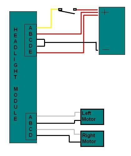
Here is how I currently have it wired:
A.) Switched 12+ (Emulating headlight switch) This is a normally open push button switch. It completes the circuit when held down.
B.) Constant 12+
C.) Nothing connected
D.) Ground
E.) Constant 12+
A.) L Headlight Motor lead 1
B.) L Headlight Motor lead 2
C.) R Headlight Motor lead 1
D.) R Headlight Motor lead 2
If anybody could provide insight to why this is occurring please let me know. I appreciate any help you can provide.
Joined
·
753 Posts
Discussion Starter · #2 ·
Something else I may add... The lights and control module were said to function properly when removed from the car.
Joined
·
753 Posts
Discussion Starter · #3 ·
I've found this page that has a little more insight on the swap: http://www.mcspeed.homestead.com/Our_Products.html
I'm having a hard time completely trusting what they're saying given the diagram I posted previously, although they seem to be very knowledgeable on the subject. I'm simply worried about frying my control module and want to be 100% certain before I make any changes to how I have it wired.
If using the 93-02 Firebird module (Part # 16525685) the wiring is a bit different. The up signal is wired exactly the same and can be done using the stock C3 headlight switch. The down signal is accomplished by simply grounding terminal "C" on the Firebird control module. This will cause the lights to drop as soon as they are turned off, even if the parking lights remain on.
This is stating that I should ground C when I want the headlights down, although looking at the diagram it appears to be a 12V+ feed coming from the tail lights fuse 
Joined
·
1,026 Posts
I re-tried a '94 module on my '89 motors tonight and grounding "C" did the trick! and yes the wiring diagram shows C as a power connection. go figure?
The module cuts power only after the motor stalls, so try holding the shaft a little tighter ( I clamped a cresent wrench on the shaft and it jammed on the housing to cause it to stop.
It is also good to see that a 84-89 Corvette headlight switch should work with the earlier module, and that the newer module will work with the earlier motors.
TTFN
Mat
Joined
·
753 Posts
Discussion Starter · #5 · (Edited)
Thanks for your help Mat. I'm really glad to see that is working for you.
I've tried this setup again today, wired up exactly as I have it in my original post. As soon as it's powered on the headlight motor begins to spin. I held the motor to the point of stall for about 2 seconds and it still wanted to run.
In your testing, how long do you have to hold the motor before the control module shuts it off?
Another question this brings up. Did you do your testing inside or out of the car? I'm simply trying to use a 12V source outside the car and wire the headlight module as a stand alone system. I have no other electrical load on the system. Is this something that could only be mocked up inside the car?
Joined
·
1,026 Posts
My test was outside the car. Just a couple of jumper wires to a battery, with terminals B&E twisted together.
I had a cresent wrench on the stem. The motor went until the wrench jammed on the motor housing. FWIW The service manual says 6 seconds.
TTFN
Mat
Joined
·
753 Posts
Discussion Starter · #7 ·
This is really starting to confuse me. Maybe I somehow managed to screw up my control module? At any time did you have 12V+ hooked up to terminal C? I wired it that way due to the diagram I found previously. I also errantly had the headlight motors wired backwards at one point. I don't think it would make a difference, although I guess you never know. Currently they are correct to the diagram I found.
I couldn't get the motor to stop after holding it for approximately 8 seconds with my 12V power supply. Thinking a battery may provide better amperage, or slightly more voltage, I tried it jumpered off a car battery. I ended up with the same results.
I've tried it with both nothing and a ground wire hooked up to terminal C. Regardless of the headlight switch position or how I'm using terminal C I can not get the motor to try to stop turning. Maybe I should try holding it for 30 seconds or so to see if it ever stops. I'm sure I have to be missing something, I'm just unsure of what that is right now.
Joined
·
1,026 Posts
Don't sweat it Ryan I do not think you burned the module. I'm sure I had C connected to power at some point and the motor polarity does not matter, you will likely have to change it to synchronize the system anyway.
Continue with mounting the motors ETC. then try it in the car. once it is together and if it doesn't work I can send you my module to try.
TTFN
Mat

Joined
·
2,050 Posts
if you really get stuck, see if you can email him: http://shbox.com/1/4th_gen_tech1.html or read up on his site.
He's a 4th gen electrical guru and can probably help you out good. You may also want to post on www.cz28.com where he usually hangs out.
-Jason
Joined
·
753 Posts
Discussion Starter · #10 ·
Jason,
Thanks for the additional link. I'll have to do a little bit more research over there as well.
Matt,
Thanks for offering your known good module to test. Unfortunately I'm quite a ways away from actually being able to mount the headlight doors to test so it will be a while before I'm able to test in the car. Just to make 100% sure I understand the wiring in your test, can you take a look at this crude MSpaint rendition of my wiring?
Joined
·
1,026 Posts
That looks like the wiring I tried (only the picture is a lot neater). Try it in the car you should be O.K. and send picture of how the motor mounting worked out, I would like to see.
TTFN
Mat
Joined
·
753 Posts
Discussion Starter · #12 ·
Well, if it's like you've tested, I'll just roll with it :thumbsup:
Thanks for the input. I'll let you know how it turns out.
Joined
·
26 Posts
Just FYI. I believe I figured out a way to wire these directly off of a standard light switch. From what I am reading the headlight switch was configured so that the parking lights would either stay on when the headlights were on or turn off when the headlights were turned on (Depending on what connection at the switch your using). Here's my proposal. If you use two relays in series. One should open and close the coil based on the dash lights circuit. The other off of the parking lights off when headlights on circuit. If wired correctly both the dashlights would have to be on and the parking lights off (extra connection for parking lights off used) to throw the relays to complete the circuit and open the hide away lights. No extra switches!!!!! Only drawback is that if you dim your dash lights too much it will open the relay. Anyway, I will let you know when I finish this. Still doing body work and won't be ready to do this until later date.
Joined
·
10,515 Posts
Just FYI. I believe I figured out a way to wire these directly off of a standard light switch. From what I am reading the headlight switch was configured so that the parking lights would either stay on when the headlights were on or turn off when the headlights were turned on (Depending on what connection at the switch your using). Here's my proposal. If you use two relays in series. One should open and close the coil based on the dash lights circuit. The other off of the parking lights off when headlights on circuit. If wired correctly both the dashlights would have to be on and the parking lights off (extra connection for parking lights off used) to throw the relays to complete the circuit and open the hide away lights. No extra switches!!!!! Only drawback is that if you dim your dash lights too much it will open the relay. Anyway, I will let you know when I finish this. Still doing body work and won't be ready to do this until later date.
Huh? I think you're making it way more complicated than it needs to be. I'm running the Firebird module with the stock non-RS headlight switch, and it works great. Wire both B & E from the diagram above to battery power. The busbar on the horn relay is convenient. Wire A to the light blue wire going into the dimmer switch. C & D to ground. That's it - no relays needed. Headlights on (high or low beam) doors open. Headlights off, doors close. Parking lights only - doors stay closed.
Edit - Rereading your post, are you contemplating doing this with just a couple of relays and no module? If so - please say. The problem would be that the motors wouldn't shut off, they'd just stop, but still try to operate. The Firebird module has some sort of load sensor in there that shuts off power to the motors when they hit the end stops.
Joined
·
26 Posts
Edit - Rereading your post, are you contemplating doing this with just a couple of relays and no module? If so - please say. The problem would be that the motors wouldn't shut off, they'd just stop, but still try to operate. The Firebird module has some sort of load sensor in there that shuts off power to the motors when they hit the end stops.[/QUOTE]
Okay. I am much better at making drawings than explaining things. Yes I am using the headlight motor controller module. If you view the wiring diagram there is a switch/relay shown connecting the battery to the module at connection A. This switch has to be manually thrown to actuate the doors. The set up that I am proposing will eliminate one of the steps. (Flipping a switch to open the doors). Here is a link to another post were they mention this toggle switch http://www.camaros.net/forums/showthread.php?t=169781. Make more sense now? Do you have any suggestions on how to wire the module up so it can be controlled by the headlight switch? Love to hear it.:thumbsup:
Joined
·
10,515 Posts
OK - I think I understand your confusion. In the wiring diagram above, the switch that is shown in wire "A" IS the factory dash mounted headlight switch. It is not not an extra switch in the system.
The place to tap into the headlight switch is the light blue wire that runs from the headlight switch to the dimmer switch. With the headlights off, there is no power to the light blue wire. With the headlights on (either high or low beam) the light blue wire is energized and the module will open your doors, then shut off power when it senses resistance. Turn the headlights off, and the doors close, then shut off when resistance is sensed.
No extra switches or relays are needed. Just the Firebird module and wiring it to the stock headlight switch.
To summarize from the diagram above:
A - to the light blue wire between headlight switch and dimmer switch, spliced in.
B & E - to positive battery power. This needs to be hot even with the car shut off. That is why the busbar on the horn relay is so convenient - it is wired directly from batt +.
Note - you "could" wire this connection through a relay with a "key on" 12v source. Mat Klemp and I discussed this via PM, and I think that's how he does it. He told me that the Firebird didn't use a relay here - just wired it hot. I have mine w/o relay and have noticed zero battery drain. It's your choice. This connection should be fused, however. (my opinion!) You could do an inline fuse. I used a fusible link.
C & D - chassis ground
On the ABCD motor harness you'll probably have to mess around with polarity to get the motors turning in the directions you want. The motors need to spin in opposite directions of eachother.
FYI - The factory wiring has the parking lights on at the first detent in the headlight switch, and they stay on with headlights on. With the wiring described above, the parking lights have no effect on the headlight doors.
Hope this makes sense.
Joined
·
26 Posts
That makes a lot of sense!! Thanks BPOS!!!!!! :beers:
Joined
·
7 Posts
I'm trying to do this same conversion. I have everything hooked up and wired to the driver's side motor for now to make sure everything works and to work out any kinks, and I've run into a kink.... I've connected "B & E" and run a wire from them to the ACC in the fuse box. Now when I turn the key to ON or ACC the motor instantly tries to open or close without turning the headlights on. But if they open they won't close and if they close they won't open. I also have "A" connected to what I believe is the correct lt. blue wire coming from the dimmer switch. Help!!
Joined
·
10,515 Posts
It sounds like you have it wired correctly. Nothing should happen until 12v is applied to the "A" wire.
A couple of possibilities come to mind:
- Bad ground
- Bad module
- WRONG module. Corvette modules look identical, but are different than the Firebird modules. My research has found that the 1990-2002 Firebird modules work. There are other modules out there that also look identical - Fiero, Saturn, earlier Firebird and I believe an Oldsmobile. I do not know if any/all of these will work.
- Also - wire BOTH motors before you give up. I don't know if that will make a difference, but it might!
Joined
·
7 Posts
It's a 98-02 Firebird module. I'll try a different gound and hooking both motors up. Is it possible that I have the wrong lt. blue dimmer wire or is the fact that the doors are moving suggest that I have the correct one? Thanks!
Posted by: irenehorita.blogspot.com
Source: https://www.camaros.net/threads/4th-gen-firebird-electric-headlight-conversion.114461/